“Low-Side” Capacitive Coupled Tesla Coil
I have been doing a lot of experimenting with Tesla coil counterpoises since March 2021. This route of experimenting has slowly morphed into “low-side” capacitive coupling of a Tesla coil resonator. To explain this, consider the high voltage terminal of a Tesla coil. The top terminal, top load, or simply the top of the resonator, is at a high potential. The lumped and distributed capacitance of the resonator is normally considered to go from the top of the resonator to ground. The ground is essentially the low side terminal of a capacitor. A metal object near the resonator at ground or near ground potential also becomes part of the low side terminal of the capacitor, thus the term low-side capacitive coupling.
I have made dozens of different versions of this topology. From a spiral 10-turn coil around the length of resonator (or inside the resonator), to a grid of vertical wires, aluminum foil of various sizes, to a sheet of copper of various configurations and dimensions. One thing this always does is increase the effective capacitance of the resonator, decrease the effective inductance of the resonator, and decrease the pure resistive impedance of the resonator (voltage and current are in phase at Fr, simulating a pure resistance with no reactance to the source of EMF). Depending on several different factors, sometimes the pure resistive component of the impedance can get much less than the DC resistance of the wire in the resonator! I’ll admit that I don’t really know how this is happening at this time.
I call the low voltage terminal a “shield,” for the lack of a better word, because there is very little electrical field on the outside of the low voltage terminal (the side away from the resonator). As an example, say your shield has twice the diameter of the resonator. You will find that the resonator still has all the properties of an unshielded resonator (standing waves at different frequencies, current distribution in the wire, etc.), but you can get your body and hands right next to the shield with very little if any capacitive effects on the resonator. In extreem cases I have been able to collect close to 98% of the resonators capacitive current in the shield – there is basically no external field. High voltage insulation becomes a problem!
From what I have described you may be thinking that a shield is very beneficial, but you don’t get something for nothing! You are not going to get a 10 kilowatt spark without putting 10 kilowatts into it! Since the capacitance increases and the inductance decreases, you will generally get a drop in output voltage. And in some cases you may get a rise in output voltage! Output impedance will probably be lower. Remember, it’s all about impedance matching! Hopefully this post will get you thinking of some new ideas.
But enough of my blabbering for now. Below are some experimental results!

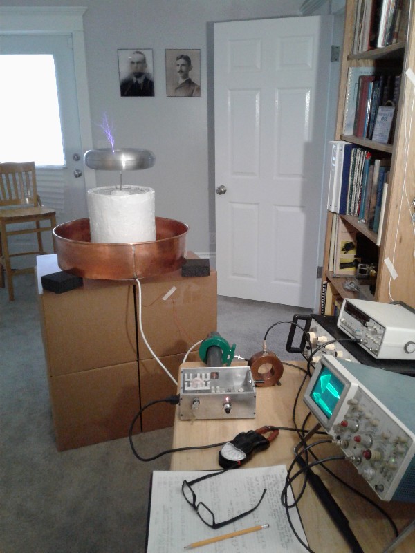
Above is a general view of a Tesla coil with “low-side” capacitive coupling. Some of the components are from my September, 1991 article in Radio-Electronics. The driver and resonator are somewhat obsolete by todays standards. The driver is a half-bridge made with bipolar transistors that puts out maybe 1700 volts at up to about 1.5 amps. The output high frequency is modulated with a ½ sine wave 60 Hz source. There is no adaptive frequency control. The resonator is a 5-gallon bucket wound with #30 wire for a length of 10.5 inches. The DC resistance of the wire is 269 Ohms. The new thing here is the shield around the resonator. The shield is a 6” high and 72” circumference piece of .021” sheet copper. Some 3/8” copper tubing is soldered to the top of the sheet copper to reduce the potential gradient and stop arcs from forming at the top of the shield. There is a gap of about 1/16” in the shield so it does not act as a shorted turn around the resonator. The resonator base is grounded and high voltage from the driver is going to the shield. The important parameters of the system are as follows:
1. Fr = 84.7 kHz
2. L = 174 mH
3. C = 20.3 pF total (10.6 pF between toroid and surrounding ground and 9.7 pF between toroid and shield)
4. X = 92.5k Ohms
5. Z looking into resonator base = 369 Ohms
6. Z looking into shield = 1622 Ohms
7. Capacitive shield current = 48% of resonator base current. This isn’t too hard to visualize. Conversley, however, if X current is forced into the shield then the resonator base will have 2.13 times X current. I had a little harder time grasping this last concept.

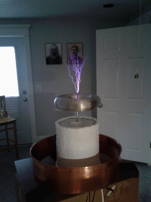
The above photo is another view of the low-side capacitive coupled Tesla coil. With an RF output of about 1700 volts the driver will force about 1.1 amps peak into the shield. The output sparks are relatively loud and they start at the side of the toroid and quickly move to the top of the toroid because of heated air. Base current in the resonator here is about 2.4 amps peak. I have never been able to get this much current into the base of this particular resonator with the driver before! It will make a 10.5 inch spark to a 1” diameter grounded ball. After the initial spark the impedance of the shield is too high for the driver to push the spark farther. The 120-volt line current here is close to 2 amps.

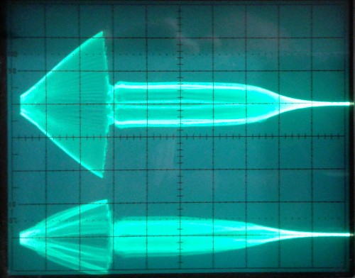
The above photo is an envelope view of the base current in the resonator and the shield current with low-side capacitive coupling. Resonator current on top at 1 amp/div and shield current on bottom at 1 amp/div. Horizontal time base = 1 ms/div. Even though the resonator base current is divided between the capacitive earth current and the capacitive shield current, it seems like the peak output voltage is still equivalent to the inductive reactance multiplied by the resonator base current, Vtop = Ibase*2*pi*F*L, or about 222 kV peak in this case

The above photo is with the base of the resonator being driven with HV and the shield grounded. When I first tried this method it did not produce any sparks from the toroid. The 120-volt current draw was about 6 amps, but the driver could not supply the 2.4 amps peak of RF required to produce sparks from the toroid. I was able to put a 2” stand-off in the center of the toroid as a break-out point and produce sparks. The peak output voltage here is less than with low-end capacitive coupling, but once the sparks start the driver is able to pump more power into the resonator. Current here from the 120-volt line is about 3 amps.

The above photo is another view of the resonator base being driven with HV and the shield grounded. The distance between the stand-off and the ground electrode is 12.75 inches. This is a record for this resonator and driver!
The resonator base current and the shield ground current are exactly in phase. The system is a series resonant circuit and the current through each component (source, resistive impedance, inductance, and capacitance) is exactly the same at any particular instant in time. By driving the resonator base and the shield with the properly phased voltage sources it should be possible to pump several times the power into the system than what a single source of the same voltage would produce without the shield.
Most of this system and theory is purely academic at this time. The resonator base impedances and the shield impedances are relatively high. Solid state devices are low impedance, so it is difficult to match impedances with this topology. Who knows though, maybe a shield could be beneficial in cooperation with a primary coil and secondary coil system?
.