Tropadyne

The Tropadyne superhet was invented by Clyde J. Fitch in the summer of 1924. The radio has two main features that sets it apart from most other mid 1920s superheterodynes. First, the first detector and the oscillator were combined in one tube. The first detector/oscillator circuit of the Tropadyne is similar to the first detector/oscillator circuit of the Pressley. It was said that the Tropadyne would not radiate or cause interference to other receivers. The Pressley circuit should be superior to the Tropadyne circuit because the Pressley has a balanced bridge (trimmed with a capacitor) that nulls out the oscillator from the loop. I suspect that a small percentage of the oscillator current in the Tropadyne does make its way to the loop antenna.
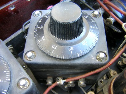
The other feature of the Tropadyne that sets it apart from other superhets is its use of user-tunable IF transformers. Each IF transformer, or “tropaformer,” as they were called, has a small knob on top that the user can adjust to peak the frequency. It was a very good idea and it wasn’t long before every superhet on the market had adjustable IF transformers (but usually not meant to be user-tunable). The high efficiency of the Tropadyne circuit eliminated two tubes from the standard eight-tube superheterodyne. Here are a few particulars of my set:
1. The circuit uses an “autodyne” first detector/oscillator (both functions combined in one tube) and utilizes user-tunable IF transformers.
2. The front panel measures 30” long by 7” high by 3/16” thick.
3. The cabinet is made of plywood and measures 30” long by 12” high (there is a 5” high cavity under the electronic chassis, possibly for storing batteries or supplies). The cabinet is similar to “A 3000-mile Superheterodyne” described in the 1926 Radio News Superheterodyne Book.
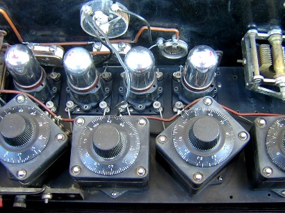
4. Tropadyne oscillator coupler and IF transformers (marked “tropaformer” on the base under the terminals).
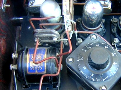
5. Karas tuning capacitors and audio transformer.
6. Benjamin tube sockets (with “QRS” UV-201A vacuum tubes).
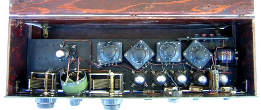
Top inside view of the Tropadyne. An antenna coupler may have been mounted on the left side of the chassis.
Close up view of the oscillator coupler.
Inside angle view.
“Tropaformer” IF transformer.
.
|
Type |
Peak Freq. |
Lower 3 dB |
Upper 3 dB |
Bandwidth |
Relative gain |
Pri. ohms |
Sec. ohms |
|
#1 |
53.8 KC |
33.2 KC |
60.8 KC |
27.6 KC |
9.8 |
17.9 |
32.5 |
|
#2 |
51.6 KC |
43.1 KC |
61.2 KC |
18.1 KC |
8.0 |
17.6 |
39.3 |
|
#3 |
54.9 KC |
43.6 KC |
67.1 KC |
23.5 KC |
6.8 |
16.6 |
33.3 |
|
#4 |
50.1 KC |
36.4 KC |
64.3 KC |
27.9 KC |
8.7 |
17.5 |
31.8 |
The Tropadyne IF transformers peaked from a low frequency of about 40 KC to a high frequency of about 80 KC. The bandpass measurements were taken at a center frequency adjusted near 50 KC. The tropaformers were somewhat difficult to adjust to an exact frequency; the signal source was set at 50.00 KC and the knob on the transformer was adjusted for a peak, then when the frequency of the signal source was adjusted (with much finer frequency control) it was noticed that the actual peak was slightly different. All the transformers were measured with A- as a secondary coil reference.
Simplified schematic diagram of the Tropadyne from the 1926 Radio News Superheterodyne Book.

Above is the audio amplifier. At right is the IF amplifier.


