McLaughlin/Precise

Meet the McLaughlin. This radio was one of the earliest single-dial superheterodynes ever made. The McLaughlin was very much different than the normal superhet of the times, and it was definitely ahead of the times in performance. My set was professionally made and it’s in excellent condition. Many of the parts used in this set were manufactured specifically for this set, including the cabinet and the Benjamin base panel with Benjamin tube sockets. Here are a few more particulars of this set:
1. The circuit is similar to the standard 1920s superhet circuit, but the oscillator signal is coupled into the plate circuit of the first detector instead of the usual grid coupling. The oscillator is also more advanced than the normal mid 1920s oscillator (better stability and power supply isolation). What makes this set really unique is the single dial feature.
2. The engraved front panel measures 14.5” wide by 10” high.
3. The Precise parts include the No. 1700 super-multiformer (four IF transformers in one package), No. 720 syncrodenser variable capacitors, No. 480 audio transformers, No. 1900 filtoformer (oscillator filter), No. 99 front panel and base panel aluminum mounting brackets, and probably the front engraved panel.
4. Precision Inducto-coupler (oscillator coupler).
5. General radio rheostats.
6. Benjamin base panel (made specifically for this set) and tube sockets.
7. Corbett cabinet (made especially for this set)
8. Weston panel meters.

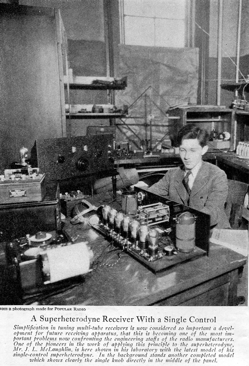
The above photo shows Mr. James Leo McLaughlin tuning his single-dial superheterodyne masterpiece. This photo accompanied the construction article for the set in the October, 1925, Popular Radio magazine. Mr. McLaughlin was an early superheterodyne authority, and his first articles on the single dial technique appeared in late 1924 QST articles.


Above photo shows one of the Precise angle brackets that secure the base panel to the front panel.
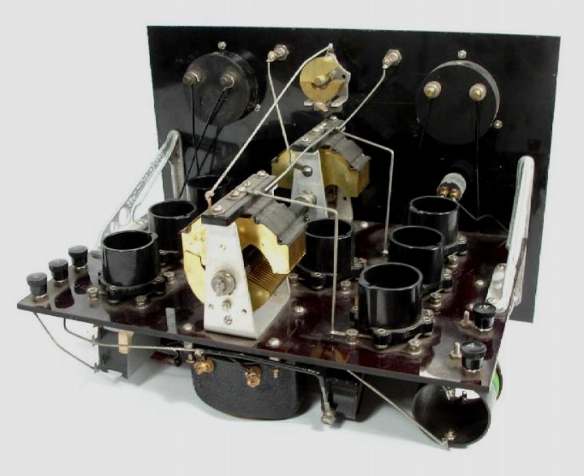
At right is a rear view of the Strait Line Frequency (SLF) oscillator tuning capacitor, a Precise “syncrodenser.”
.

Precise advertisement showing the super-multiformer from the December, 1924, Popular Radio magazine.

Another view of James Leo McLaughlin with two earlier versions of his single-dial superheterodyne designs. The superheterodyne in the background was described in a November, 1924, QST article. This photo was in the April, 1925, Popular Radio magazine.

|
Type |
Peak Freq. |
Lower 3 dB |
Upper 3 dB |
Bandwidth |
Relative gain |
Pri. ohms |
Sec. ohms |
|
#1, A+ ref. |
34.0 KC |
7.0 KC |
67.0 KC |
60 KC |
1.37 |
133.2 |
384 |
|
#2, A+ ref. |
19.0 KC |
5.0 KC |
65 KC |
60 KC |
1.25 |
141.0 |
375 |
|
#3, A+ ref. |
21.0 KC |
5.0 KC |
65.0 KC |
60 KC |
1.22 |
147.6 |
354 |
|
#4, A+ ref. |
36.6 KC |
32.5 KC |
40.4 KC |
7.9 KC |
28.0 |
137.7 |
380 |
The table below shows the bandpass measurements of the super-multiformer IF transformer bank with the secondary of the IF transformers referenced to A+. The second detector’s grid leak resistor and capacitor were in place. This comparison clearly shows how great of an effect the bias voltage has on stage gain and bandwidth.
|
Type |
Peak Freq. |
Lower 3 dB |
Upper 3 dB |
Bandwidth |
Relative gain |
Pri. ohms |
Sec. ohms |
|
#1, A- ref. |
39.6 KC |
29.7 KC |
53.9 KC |
24.2 KC |
17.2 |
133.2 |
384 |
|
#2, A- ref. |
40.2 KC |
30.6 KC |
52.3 KC |
21.7 KC |
16.0 |
141.0 |
375 |
|
#3, A- ref. |
40.7 KC |
31.5 KC |
52.8 KC |
21.3 KC |
16.0 |
147.6 |
354 |
|
#4, A- ref. |
37.3 KC |
33.6 KC |
40.5 KC |
6.9 KC |
28.0 |
137.7 |
380 |
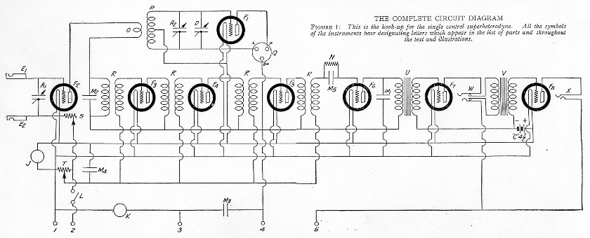
The schematic diagram of the McLaughlin single-dial superheterodyne (from the October, 1925, Popular Radio magazine).
The table below shows the bandpass measurements of the super-multiformer IF transformer bank with the secondary of the IF transformers referenced to A-. The second detector’s grid leak resistor and capacitor were in place.

The two Precise syncrodensers are the two components that make the single dial operation possible. Most of the tuning capacitors in the early 1920s had semicircular shaped plates and they were known as Strait Line Capacity (SLC) condensers. This was because a plot of the capacitance with reference to the shaft position was a strait line. Tuning a Tuned Radio Frequency (TRF) radio with multiple capacitors on a single shaft was fairly easy, because the tuned circuits were all tuned to the same frequency simultaneously. Tuning a superheterodyne was a totally different matter. In a superheterodyne, the oscillator frequency has to change at a different rate than the RF tuner frequency. Many engineers at the time thought that it was impossible to make a single dial superhet. Mr. McLaughlin solved the problem with Strait Line Frequency (SLF) tuning condensers. The shape of the plates on the tuning capacitor had to be specially made. Being Strait Line Frequency capacitors, as the two capacitors turned in unison, or synchronously on the same shaft, the difference in frequency between the oscillator and the RF tuner would always track and stay constant. This difference in tracking frequency was the IF frequency, of course.
In his 1928 edition of Modern Radio Reception, Charles Leutz states that the SLF capacitor is the only type of condenser that can be used in a single-dial superheterodyne (page 208). As it turned out, SLF capacitors were not required to make a single-dial superhet. I don’t know the entire story, but the RCA Radiola 60 of 1928 was a single-dial super, and it used padder and trimmer capacitors to accomplish the proper tracking, without the use of SLF capacitors. Even so, the McLaughlin deserves a place in history as one of the first single-dial supers! It must have been a wonderful and strange sensation in those days to tune an eight-tube receiver with a single dial!

Precise Filtoformer.


Bottom chassis view. The super-multiformer is lengthwise in the center with the audio transformers top center and bottom center. The oscillator coupler is in the bottom left corner and the filtoformer is just to the right of it.

Rear angle view of the set.

Top inside view of the set. The oscillator tube is in the upper left corner, the first detector tube is in the lower left corner, the first IF tube is in the far left center followed by the second IF tube, the third IF tube, and the second detector tube (left to right center). The first audio tube is in the upper right corner and the second audio tube is in the lower right corner.
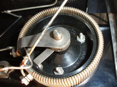
General Radio rheostat.